
 GAOERJI STEEL
Search
How To Size Steel I-Beams For A Bridge
Choosing the right steel I-beam size for the bridge is by no means a matter of beating your head. This process has always been unable to get around the core logic: determining the total load, calculating the maximum bending moment and shear force, and dead-guard deflection limit.
Before making a formal calculation, you must understand that this is not just choosing a steel part, but laying the foundation for the life and safety of the entire bridge. The following is my detailed dismantling of the sizing process of steel I-beams in actual operation:

Step 1. Determine The Total Load
The first step in sizing is to cut out all the forces that may be pressed on the beam. Missing any small static load will be amplified in the structural performance later.
- Dead Loads: refers to the “dead weight” of the bridge structure itself. In addition to the I-beams themselves, you also have to count the bridge decks (whether concrete, wood or steel grating), railings, street lights and any permanent accessories.
- Live Loads: These are the variables that are moved. For bridges, it is passing vehicles, pedestrians, and environmental loads such as wind and snow.
It is important to calculate these total weights because the total load directly determines the required section modulus of the beam.
Step 2. Accurate Calculation Of Bending Moment And Shear Force
After the load is set, it depends on how the beam will be bent.
- Bending moment: This is a force trying to bend the beam downward. For simple equal-span bridges, the maximum bending moment usually occurs at the central location.
- Shear force: This force is concentrated near the points of support (I. e., the ends of the bridge), and the beam must be strong enough to resist the risk of being “cut off” by the vertical load.
You must ensure that the cross-sectional design strength of the selected steel is stable to cover the calculated maximum stress.
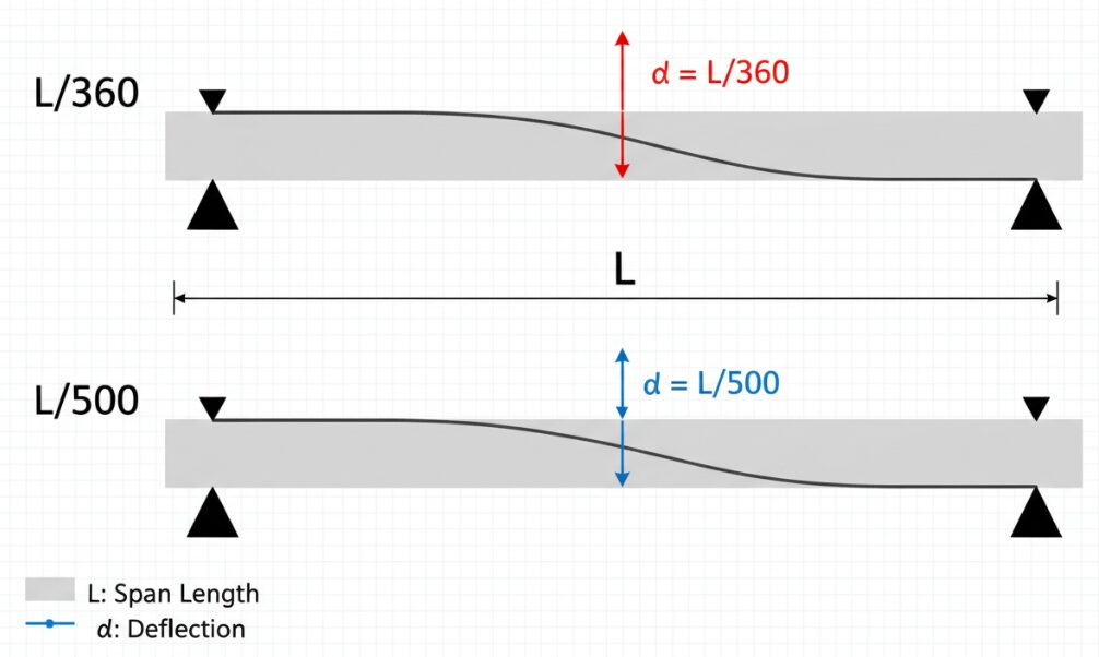
Step 3. Deflection Limit
Many people to confuse the standards of buildings and bridges. Bridges need more stiffness to suppress the “bounce feel” or vibration. If the car shakes badly in the past, it will not only cause structural fatigue, but also make the driver feel uneasy. The L/500 standard means that for a 50-foot bridge span, the beam cannot deflate more than 1.2 inches at maximum load. In some projects with heavy traffic or high precision requirements, I will even push this limit to L/800.
Step 4. Preliminary Sizing
Before throwing data into a complex simulation system, I will narrow down the choices. A height-to-span ratio between 1/25 and 1/30 is the golden rule for preliminary sizing.
If you were to build a bridge with a span of 30 feet, the beam height would need to be about 14 to 15 inches on a scale of 1/25. This gives you a very clear direction—go directly to the W14 or W16 category of wide flange beams to find a solution.
Steel Structure Workshop
Steel Structure Workshops offer versatile designs. Clear Span ensures unobstructed space, while Centre and Intermediate Columns provide economical solutions for wide spans.
Bridge/Steel Structure Bridgeipsum
Steel Structure Bridges utilize high strength-to-weight ratios to achieve long spans where intermediate supports are difficult.Their versatility makes them essential for critical infrastructure connectivity.
Steel Structure Buildings
Steel Structure Buildings feature versatile designs to meet diverse needs. Clear Span offers open space, while Centre and Intermediate Columns increase economy for large spans. Multi Gable accommodates complex widths.
Step 5. Selection Of Wide Flange Beam And Yield Strength
In the field of bridges, wide-flanged beams are worthy protagonists because of their extremely efficient handling of bending moments.
- Yield strength: Stop holding on to the old A36 steel. Most of the current standards are ASTM A992, which has a yield strength of 50 ksi and a strength-to-weight ratio far exceeding that of older materials.
- Span table and software check: after selecting the material grade, the last step is to take your calculated bending moment, shear force and deflection requirements, check the span table of the local, or use professional software for final confirmation.
Every technical link from load analysis to material selection is to ensure that these steel beams can carry the specific needs of the project in a tight fit. If you go astray in the preliminary estimation, the following detailed design will only get twice the result with half the effort.
Author: Robert Harrison, P.E.
“I am a structural engineer with over 11 years of experience specializing in steel bridge design and infrastructure projects. Throughout my career, I’ve balanced the precision of modern simulation software with the reliability of time-tested empirical formulas.”
The prev: Are Steel Buildings Cost EffectiveThe next: How To Build A Steel Roof
Related recommendations
-

How To Frame With Steel Studs
171Learn How To Frame With Steel Studs. Master Layouts, Track Installation, And Safety For Professional, Lasting Walls.
View details -
What Is A Moment Connection In Structural Steel
9Master Moment Connections To Build Stable, Open, And Seismic-Resistant Steel Structures Using AISC Standards.
View details -
How Steel Buildings Can Save Money
198Learn How Steel Buildings Can Save Money: Cut Build Costs By 40%, Lower Insurance Premiums, And Maximize Usable Space.
View details -
How To Wire A Steel Building
218Discover How To Wire A Steel Building Safely. Use Beam Clamps, Magnetic Mounts, And Mc Cable For A Code-Compliant Install.
View details


HelloPlease log in